Structural Plan Symbols. Steel it was once the largest steel.
Structural Steel Drawings
The selection is yours.
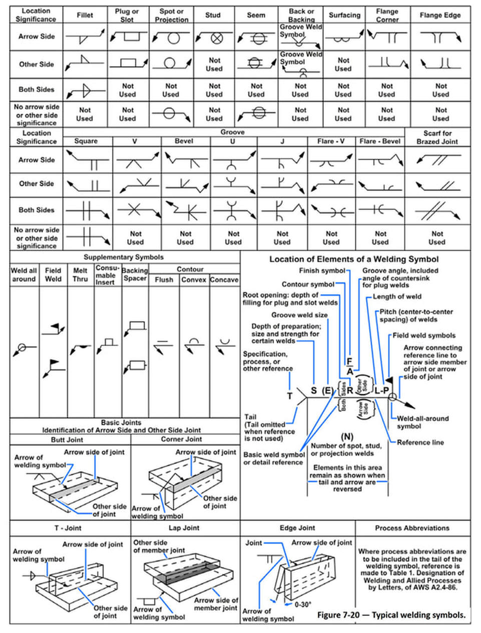
. AE ARCHITECTENGINEER ADDNL ADDITIONAL B BOTTOM BO. A drawing of a typical welded steel truss is illustrated in Figure 7-24. However the symbols below are fairly standard at many offices.
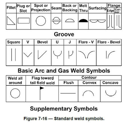
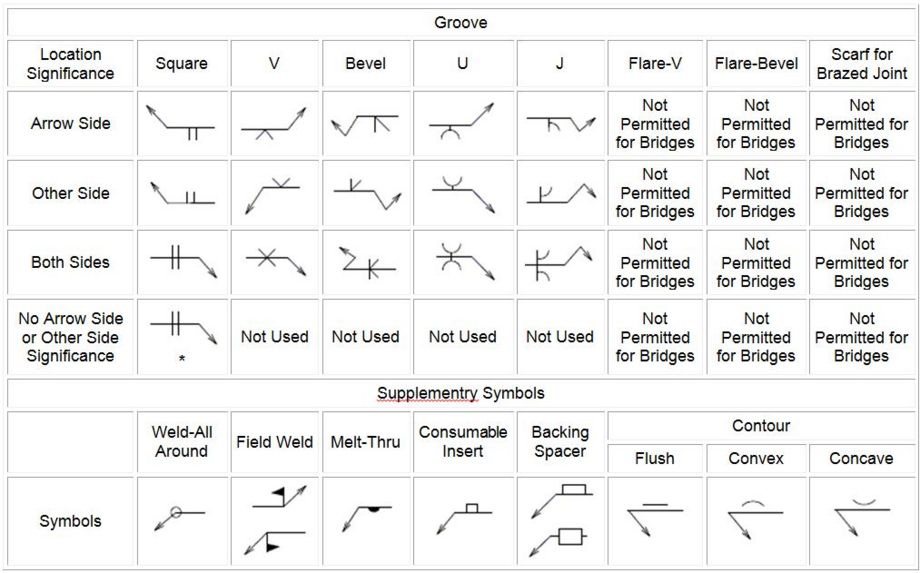
Name Double sided V butt Double sided bevel butt Double sided U butt weld Symbol. Old Designation for Tube Steel no longer. Bar notation gives the following information in this ordernumber of bars.
When you interpret the welding symbols you will see that most of them show that the structural angles will be fillet welded. Structural steel comes in various different shapes. Structural grid indicator structural grid line 1 2 b a revision area revision number symbol 1 1 base plate mark spot footing mark symbol 1 f1 bp1 spot footing mark base plate mark cf1 continuous footing mark wall mark symbol w1 wall mark 0 4 8 16 0 4 8 16 sideplate moment connection symbol see sideplate drawings ae architectengineer ab anchor bolt aban abandon.
Symbols and abbreviations for concrete as per aci general existing construction north 1 sd package - 03-30-11 5 symbol legend structural abbreviations s210 foundation plan s501 foundation details s502 steel details s220 roof framing plan dd package - 04-08-11 5 s503 6 permit - 04-22-11 revisions - 06-06-11 3 steel stud details 7 permit review - 06-27-11. An Explanation of the Basic Welding Symbols With Charts - Google Docs. Spacing mm if required.
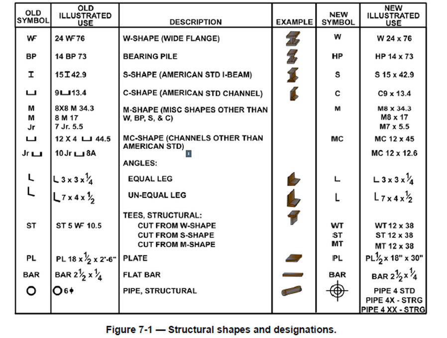
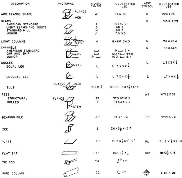
For example the symbol ST 5 WF 105 means the tee has a nominal depth of 5 inches a wide flange and weighs 105 pounds per linear foot. A brief tour of a set of structural design drawings for a building from the perspective of a structural engineer. Hollow Structural Shape 9.
Aside from the simple length markings there are many other symbols that can be seen on structural steel fabrication drawings depending on the type of assembly and material. Structural steel drawing symbols Often youd like an unique and at the same time a straightforward nail design. Structural Steel Drawing Symbols.
This list includes abbreviations common to the vocabulary of people who work with engineering drawings in the manufacture and inspection of parts and assemblies. Depth in Long Direction 5. Architects Scales and Sizes 16 Scale Full Size 12 1- 0.
Lap reinforcement only at locations shown in the drawings. The list of abbreviations used in a set of structural drawings varies from office to office. A span direction symbol for a structural element.
Ie a permanent steel pan formwork for a suspended concrete slab. Concerning welDing anD suBsequenT Touch-up oF galvanizeD sTeel is availaBle in The american galvanizers associaTions aga Welding Hot-dip galvanizing puBlicaTion. For example symbols representing sections or heights common signs include circles rectangles triangles etc.
WelDing symBols are Those DeFineD in aws a24-2012 Welding. Many Structural Engineering detail drawings are read using the Architects scale. Thickness of Shape NON Standard AISC Call Out.
Structural steel is fabricated or erected a plan of action and sequence of events be set up. A structural tee is made by slitting a standard I- or H- beam through the center of its web thus forming two T-shapes from each beam. The optimal Alternative is the designs with the nails with hearts.
It could be a multicolored scattering of tiny drawings or one coronary heart on the accent of the finger. Refer to the symbol legend sheet for special symbols used in a particular set. The intent of this video is to provide ins.
This for example is an angle symbol showing under what angle should two pieces be merged. CENTER LINE CMU CONCRETE MASONRY UNIT CONC. Grade of steel used for rcc works shall be fe500tmt.
Australian Steel Institute Structural steelwork standard drawing notes 1st ed. The information presented by the Australian Steel Institute in. For example you can use this to show the span direction of Bondek Condek Kingspan etc.
The plans sequences and required materials are predetermined. Architects scale always reads X 1- 0 For example ½ 1- 0 or 3 1- 0. The fillet will have a 14 inch radius thickness on both sides and.
Engineering drawing abbreviations and symbols are used to communicate and detail the characteristics of an engineering drawing. Width in Short Direction 58. Aside from the simple length markings there are many other symbols that can be seen on structural steel fabrication drawings depending on the type of assembly and material.
2-0 roof joist beam roof joist step foundation step height detail number. Drawing Numbers All drawings will be numbered using the standard designation for structural drawings. DIMENSION DWG DRAWING EF.
BOTTOM OF BLDG BUILDING CL. For example the symbol ST 5 WF 105 means the tee has a nominal depth of 5 inches a wide flange and weighs 105 pounds per linear foot. Some of the most popular are L-shape Z-shape structural channel and many others.
Steel structural Standards Australia 2Building Iron and steel Specifications - Australia Disclaimer. Square butt Square V butt Square V butt with broad root face Single bevel butt Single bevel butt with broad root face Single U butt Single J butt Symbol. A useful AutoCAD block for structural drafting.
Think of it like a road map providing guidance while you go through the construction. A structural steel drawing is an engineering plan that spells out how the building will be erected. All drawing are numbered consecutively with a letter S preceding the number S-1 S.
Reinforcement is represented diagramatically and not necessarily in true projection. Be sure to check the front section of the drawing set for the abbreviations used within. Learning the symbols meaning on steel structure drawings plays a critical role in reading the drawing.
Structural symbols and legend moment connection north arrow span direction section detail mark elevation mark recess or step in slab plan detail mark plan note column grid line column and foundation type marks sloped surface pitched roof tilt-upprecast concrete wall wall types sf. HSS Fy42ksi TS Fy42ksi Standard AISC Call Out. GENERAL NOTES ABBREVIATIONS SYMBOLS LEGEND.
Each structural engineering office uses their own set of plan symbols. Symbols Commonly Used in Structural Drawings Strength. We also have another article that can help you identify structural abbreviations used in a drawing set.
In dimensioning the structural tee symbol is preceded by the letters ST. IF possiBle sTeelwork shoulD Be DesigneD To Be BolTeD raTher Than welDeD aFTer galvanizing.
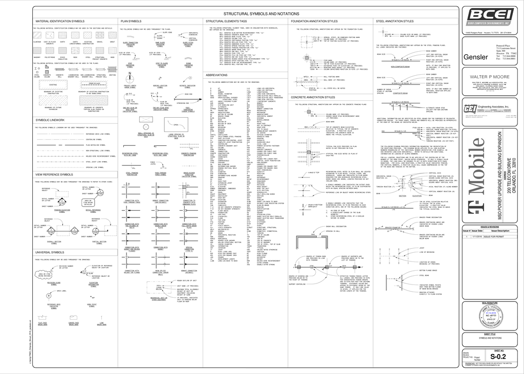
S 0 2 Symbols And Manualzz
751 5 Structural Detailing Guidelines Engineering Policy Guide
Structural Steel Drawings
Structural Steel Drawings
Chapter 7 Structural And Architectural Drawings

How To Read Structural Steel Drawings Directorsteelstructure

Structural Plan Symbols Archtoolbox

Pin On Civil Engineering
0 comments
Post a Comment